| Steps |
Image |
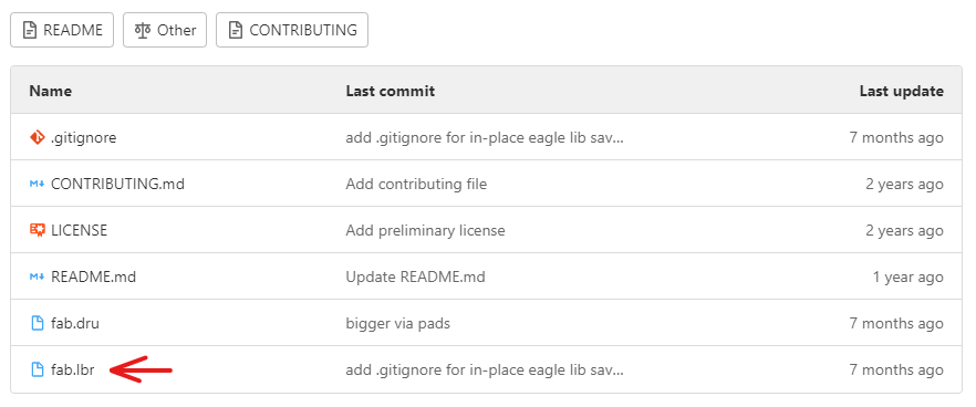
| First I have to download EAGLE and download the fab lab library from the GitHub repo |
 |
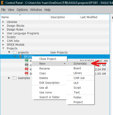
| After that i create a new project/schematic |
 |
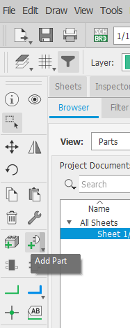
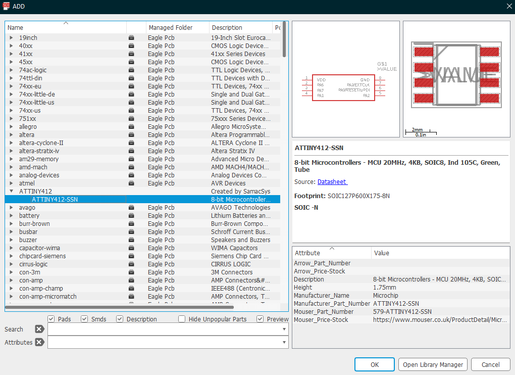
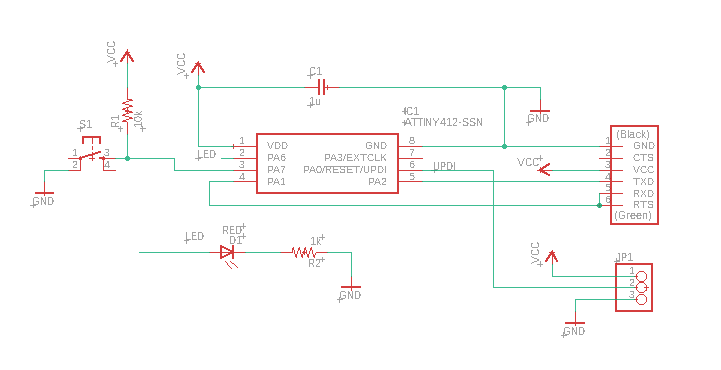
| Next, I can start adding the necessary parts for the ATtiny412 in by clicking the ADD PART and find the relevent parts than click on OK.
Components: ATtiny412 chip, Headers, Capacitors, Resistors, 1x3pinhead, etc..
|
|
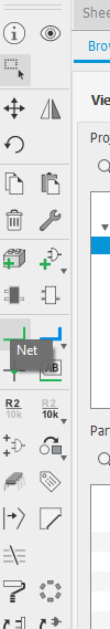
| Using DRAW(Net), I connect the parts to the ATtiny412 chip |
 |
| After connecting the components, I arrange the circuit neatly and keyed in the values fot the capacitors (1micro) and Resistors (1k and 10K) |
 |
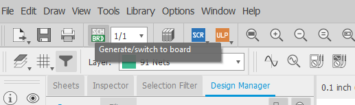
| Than I click on generate to conver schematic to board |
 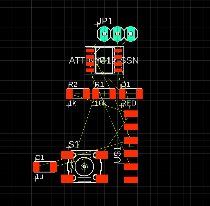 |
| After arranging the components, I set the line width to 16 using the "route" command than start connecting the components |
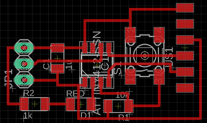 |
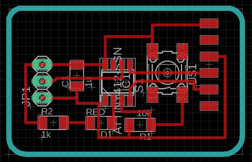
| After that the border is created, than I did a final check for any errors [ Tools -> DRC ] |
 |
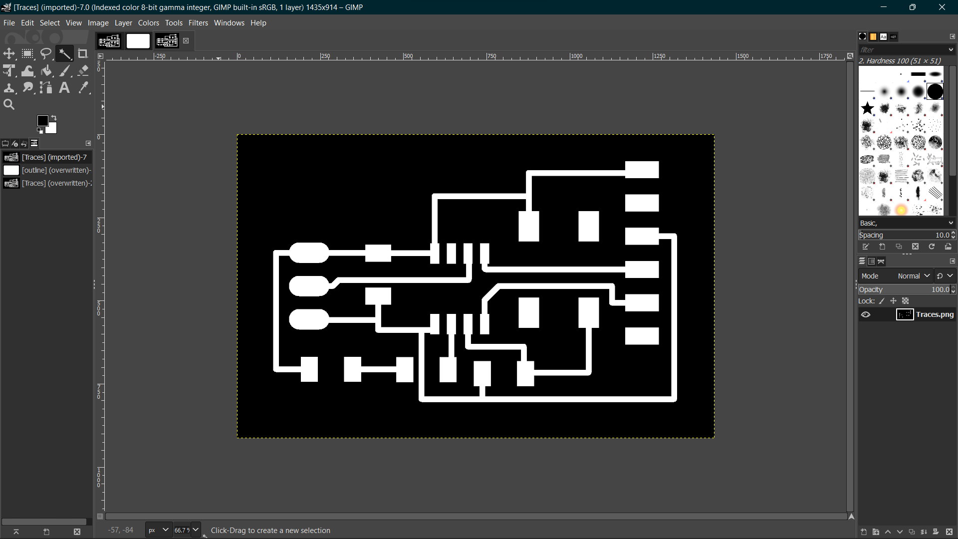
| After checking and making sure that there is no error, I off all layers except 1 & 17 and export the files as an image to obtain the traces and filled up the padholes(layer 17) using GIMP |
 |
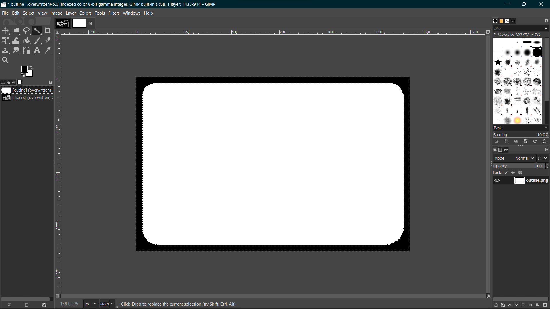
| Off all layers except 46 for the outlines |
 |
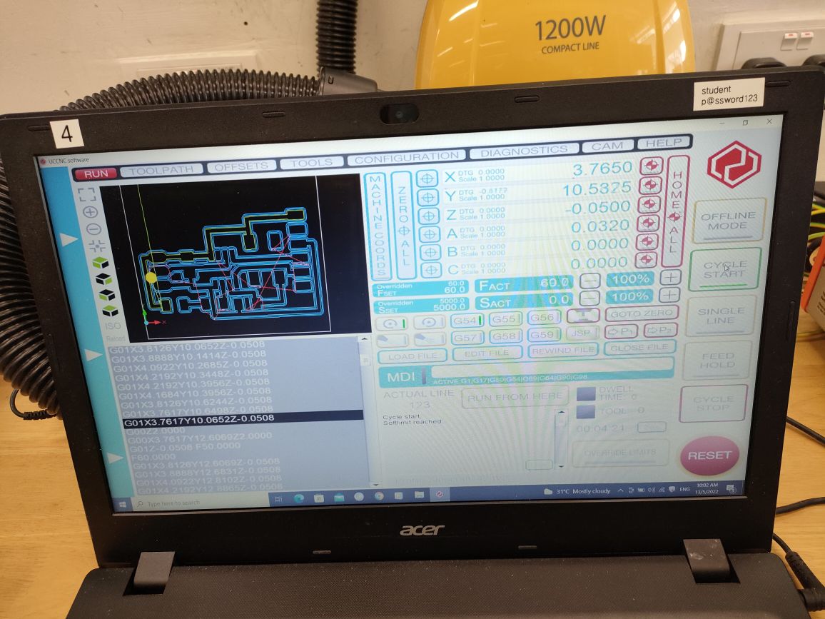
| After I import the image after editing it in gimp, I use the mod software to generate the G-code and save it in my thumb drive
than load it into the laptop and repeat the steps I did for the FTDI and UPDI |
 |
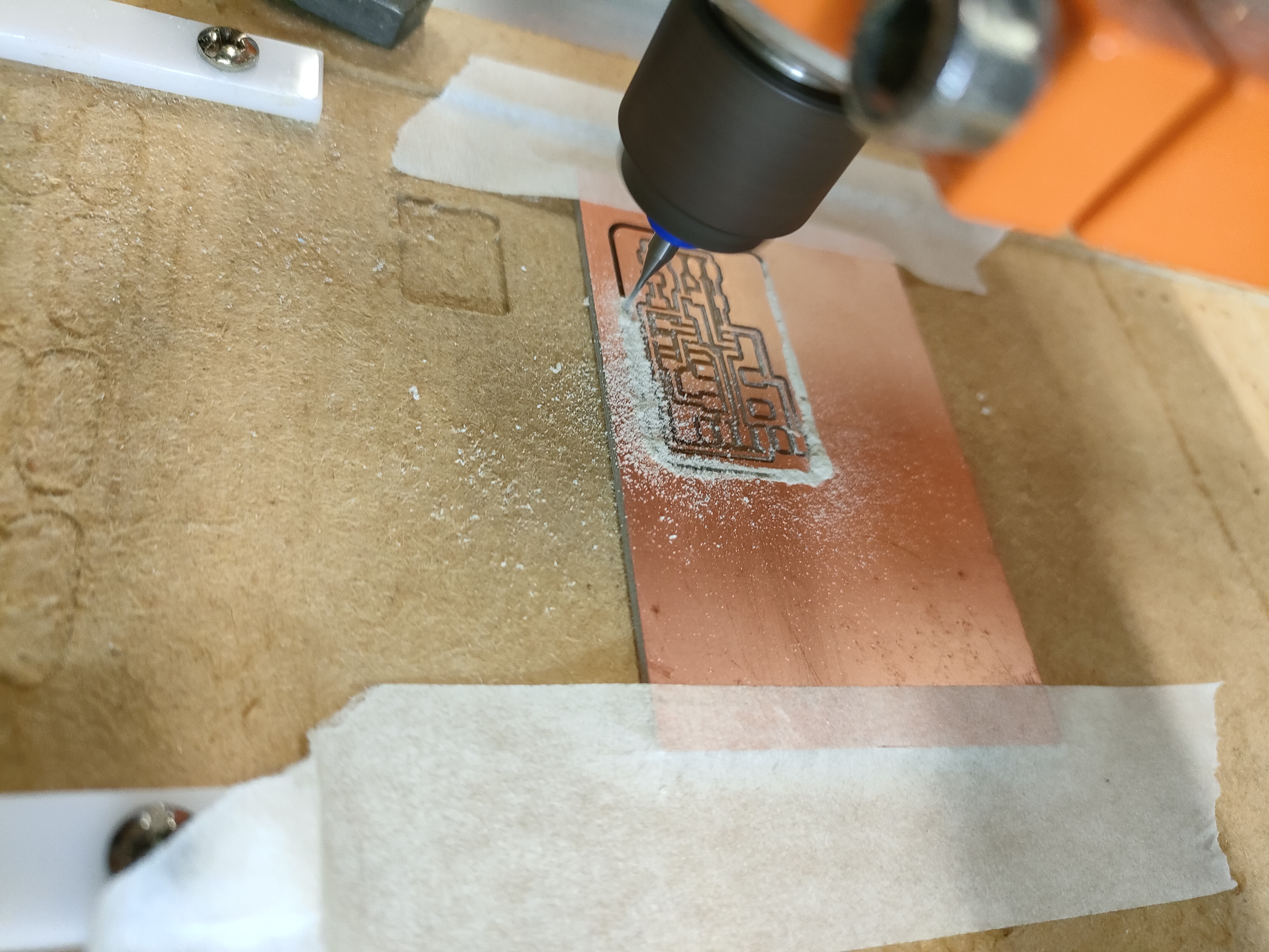
| Fabricating the ATtiny412 |
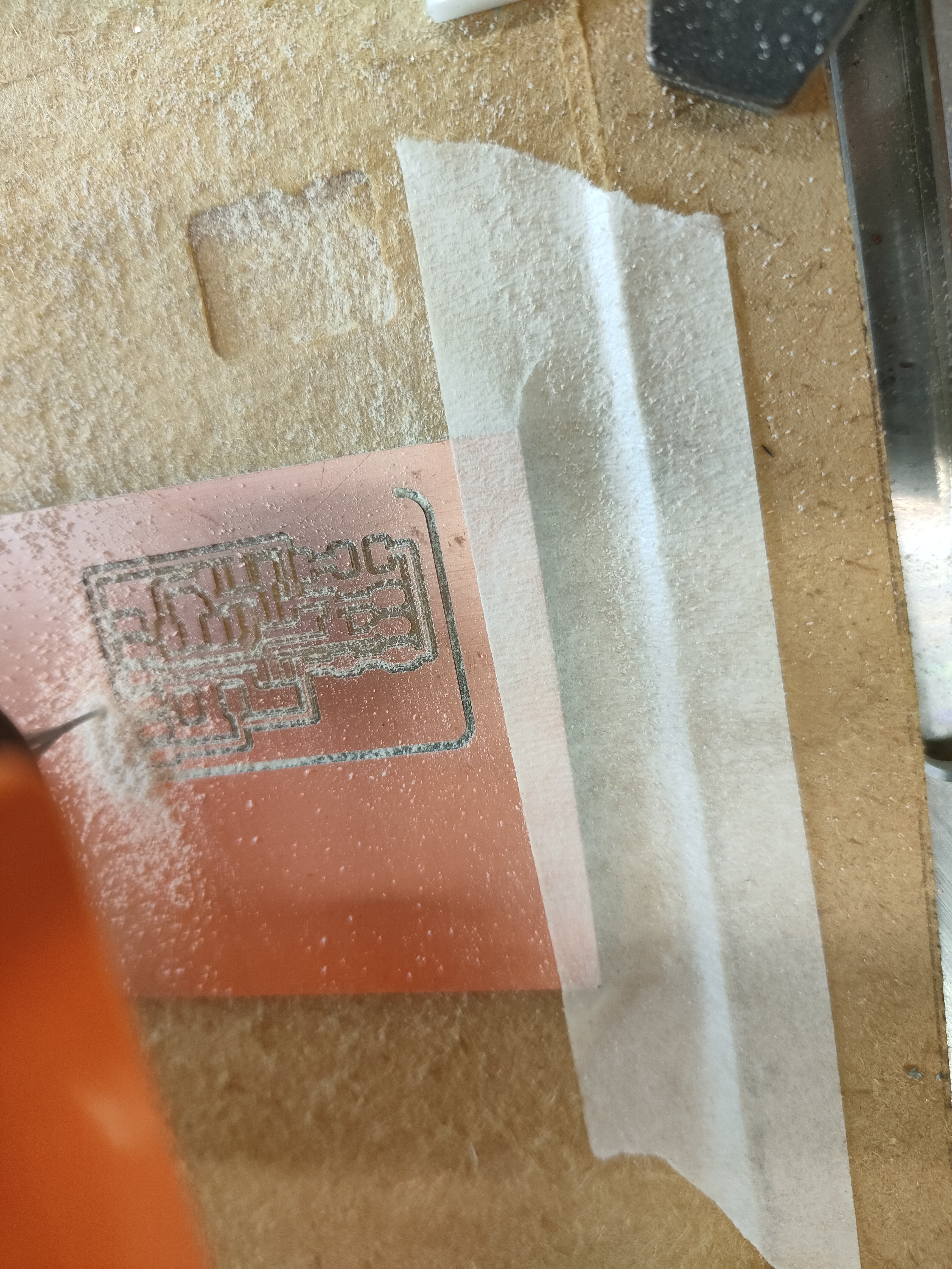 |
| Fabricating the ATtiny412 outline |
 |
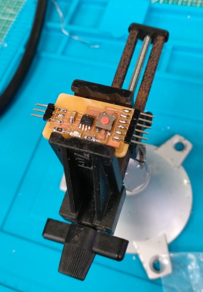
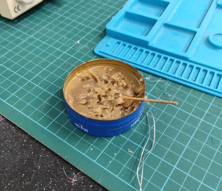
| Lastly, I had to solder the parts (LED, Resistors, capacitors, pushbutton, etc) on to the ATtiny412 board.
I had to be very careful when I solder, first I had to apply flux on to the board before soldering.
Tweezers was used to possition the parts as they are quite small. I had to use the heat gun to remove the components when I solder wrongly |
 |